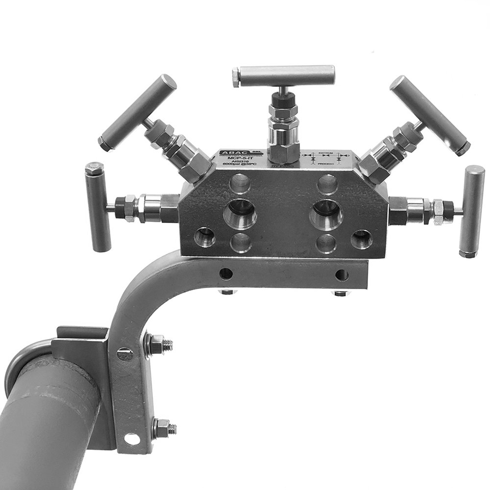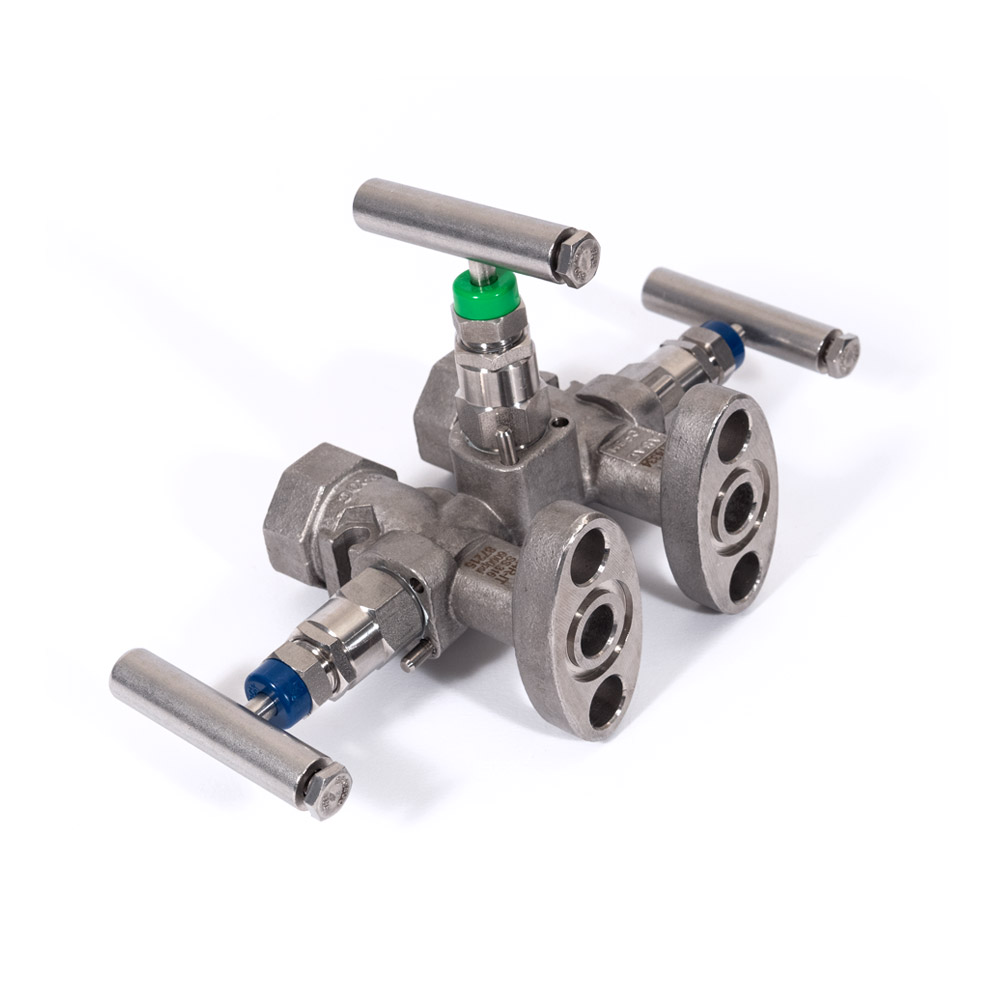
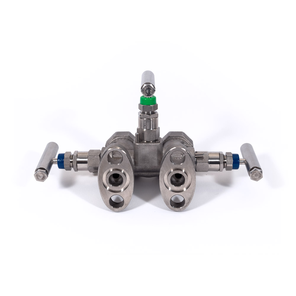
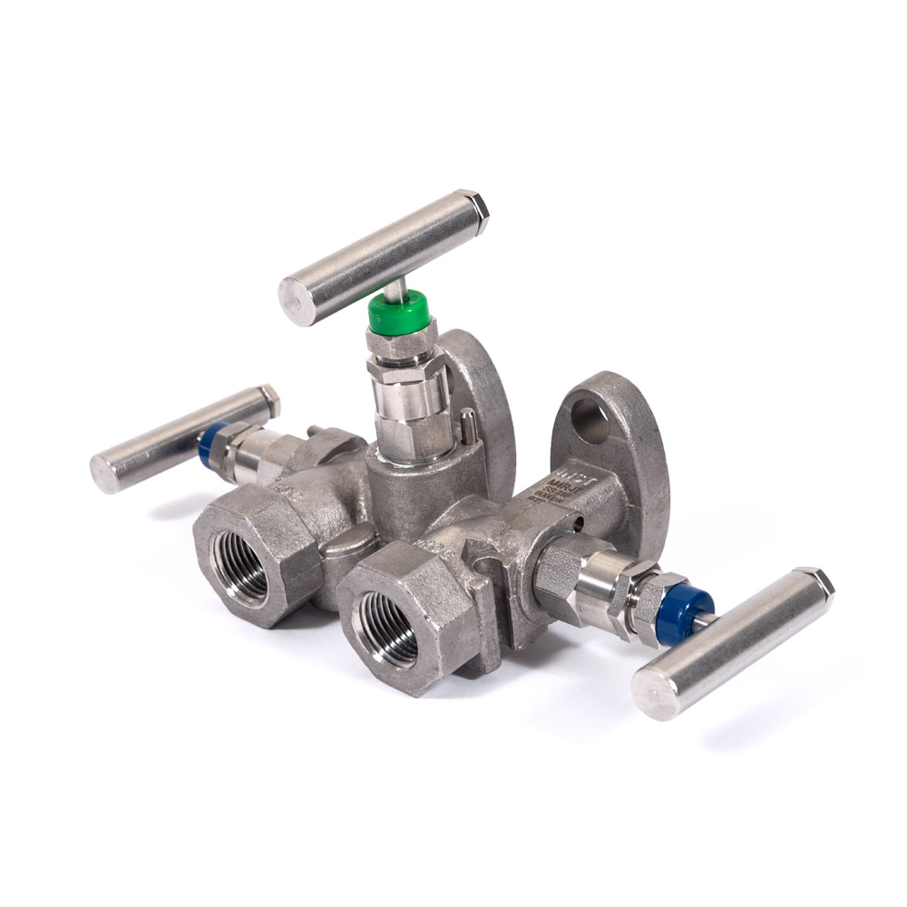
DESCRIPTION
They are 3-valve manifolds designed for the flanged transmitter mounting with a distance between connections of 2 1/8”. The instrument is directly fixed on the manifold flanged face by means of 4 NF 7/16” bolts. In this way a series of accessories is eliminated, reducing costs and leak possibilities.
FEATURES
• The M4 model is used when it is required a direct connection with an orifice plate, allowing the transmitter to be placed very close to the process pipe. In this case, the oval flanges of the transmitter are mounted on the manifold flanged face to receive the process signal through a 1/2” pipe.
• The M4R is used when it is not required a direct connection with the orifice plate. On the process side the manifold has two 1/2” NPT threaded connections to receive the signal through tubing and connector.
 Datasheet
Assembly sheet
Specifications

Service pressure @ 70 °F:
6000 psi - Standard
4500 psi - AISI 316 SS mounting bolt
Maximum temperatures:
500 °F - PTFE packing
930 °F - Graphoil packing
| Product code | Connection 1 | Connection 2 | Model | MWP (PSI) | cv | Quote |
|---|---|---|---|---|---|---|
| 113000 | FLANGE 4 | FLANGE | M4 CT | 6000 |  |
|
| 113001 | FLANGE 15 | FLANGE | M4 P CT | 6000 | |
|
| 113010 | FLANGE 49 | FLANGE | M4 CG | 6000 | |
|
| 113011 | FLANGE 52 | FLANGE | M4 P CG | 6000 | |
|
| 113200 | FLANGE 42 | FLANGE | M4 IT | 6000 | |
|
| 113201 | FLANGE 74 | FLANGE | M4 P IT | 6000 | |
|
| 113210 | FLANGE 37 | FLANGE | M4 IG | 6000 | |
|
| 114004 | FLANGE 100 | 1/2 NPT F | M4R CT | 6000 | |
|
| 114005 | FLANGE 73 | 1/2 NPT F | M4R P CT | 6000 | |
|
| 114014 | FLANGE 77 | 1/2 NPT F | M4R CG | 6000 | |
|
| 114204 | FLANGE 62 | 1/2 NPT F | M4R IT | 6000 | |
|
| 114205 | FLANGE 89 | 1/2 NPT F | M4R P IT | 6000 | |
|
| 114214 | FLANGE 25 | 1/2 NPT F | M4R IG | 6000 | |
|
| 114215 | FLANGE 85 | 1/2 NPT F | M4R P IG | 6000 | |
related products