


The monoflange valve provides a safe, simple and economical method for direct installation of pressure instruments with the process flange. They combine the function of up to three valves in a particularly compact body, thanks to a precise network of internal channels and valve chambers. But, once installed, what really happens inside a monoflange?
In a chemical process, a high response speed is required for most control applications. One of the variables that affect response time is the volume and distance between the process and the instruments. If the medium to be measured is gas and the process tends to fluctuate at times, or if control is critical, the solution is to mount the instrument close to the process.
Vibrations are also critical. The longer the connection, the greater the vibration amplitude. A monoflange includes one, two or three needle valves within a compact flange-shaped body, allowing for a significant reduction in volume, dimensions, weight and potential leak points.
In a monoflange with two valves (blocking and purging), one valve (with blue cap) isolates the process and the other (with red cap) regulates the purging of the medium trapped inside the instrument. This is mainly used in applications that are relatively uncritical (e.g. low pressure) or where a first block valve is provided just before the monoflange.
The safest configuration, and the one we recommend for aggressive media or critical operating conditions, is the three-valve single-flange or the so-called double block and bleed (DBB), which has two block valves in series and a vent valve.
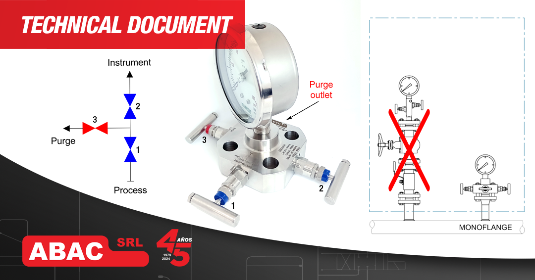
Functionality of a DBB monoflange:
• Flow enters the monoflange from the pipe and stops below the first block valve.
• When the first block valve [1] opens, the flow advances to the second block valve [2]. When valve [2] is open, the instrument remains connected to the process line.
• When the first blocking valve [1] is closed, the medium trapped between the valve and the instrument can be discharged with the help of the purge valve [3], through the purge outlet. The two blocking valves [1, 2] are in an inclined position, allowing flow to pass through them.
The two block valves allow better isolation of the process: In the event that the first block valve does not adequately isolate the fluid, the second will act as a means of safety against accidental leaks. In some cases, customer specifications do not allow fluid to be in contact with the instrument when it is not measuring. For this reason, the fluid must be evacuated through the purge line. In other cases, because of the purge line, instruments can be easily calibrated without removing them from the line.
MOUNTING
Vertical Mounting: For horizontal piping, when the process connection is vertical, the valve is mounted as delivered, bolting the flanged face into the process and threading the gauge or instrument into the top connection 1/2″ NPT Female (as in the image above).
Horizontal mounting (depending on model): In this case, the purge valve [3] must be reversed with that of the second blockage [2], and mount the pressure gauge or instrument in the 1/2″ NPT side connection (originally purge outlet).