


An orifice plate is a measuring device that has been used for many years, successfully applied to measure the velocity (and therefore the flow rate) of fluids passing through a pipe. However, it is also used to reduce pressure or restrict the flow of a fluid within a pipe.
To calculate fluid velocity and flow rate, orifice plates use the same principle as Venturi tubes: Bernoulli’s principle. This establishes a relationship between pressure and fluid velocity, concluding that as fluid velocity increases, its pressure decreases, and vice versa.
Orifice plates are thin, disc-shaped plates, usually made of metallic material (usually stainless steel), which makes them easy to install and durable. They are perforated in the center (concentric orifice). This opening, which is usually cylindrical or prismatic, allows the fluid to pass through. They are installed between pipe connections, and pressure taps are placed before and after the pipe to record the pressure difference and measure velocity.
These plates can withstand temperatures up to 1472 °F. They are suitable for measuring flow rates in liquids, gases, and water vapor. They generally have an accuracy of ±0.5% of the effective or maximum flow rate the pipe can carry.
Orifice plates are classified according to the type of orifice they have:
Concentric orifice plate: As its name suggests, the orifice is located right in the center of the disc (commonly used for clean fluids).
Conical concentric orifice plate: Similar to the previous type of plate, it differs in that the orifice area decreases as the fluid moves through it. It is generally used for highly turbulent fluids.
Segmented concentric orifice plate: This plate’s characteristic is that its orifice is not circular, but rather segmented and forms a semicircle. They are used to measure fluids containing particles.
Eccentric orifice plate: In this plate, the orifice is not located in the center of the disc, but slightly lower. They are used in small-diameter pipes.
Operation:
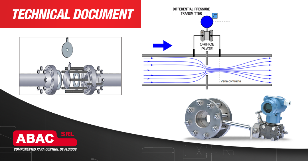
The operation of an orifice plate is simple. As the fluid passes through it, the fluid pressure decreases until it reaches the area called the “vena contracta.” At this point, the minimum pressure value is reached inside the pipe, and of course, it is the point where the fluid’s velocity will be at its maximum. After this point, the pressure will increase; however, it will never return to its previous value (before the orifice plate), due to the effects of losses caused by turbulence and friction within the pipe.
By measuring this pressure differential, the velocity can be calculated using the following formula:
V = C * √ (2 * ∆P / ρ)
Where:
V = Velocity
C: Discharge coefficient (depends on geometry and flow conditions)
ΔP: Measured pressure difference
ρ: Fluid density
HP (high pressure) and LP (low pressure) pressure taps are made using special plate-holder flanges, with 1/2″ NPT connections spaced 1″ (25.4 mm) apart on both sides of the plate. These pressure taps offer two options: Local Mounting or Remote Mounting. API RP 551 recommended practices indicate different methods for mounting differential pressure measuring instruments, using 3- to 5-way manifolds, depending on the application (dry gas, steam, liquid, etc.).
We recommend the use of 3- and 5-way ABAC manifolds for differential pressure measurement. Designed for mounting flanged transmitters with a 54 mm (2 1/8″) connection spacing. Models for direct or remote connection with the orifice flange. For more information, please refer to this catalog or contact our sales department:
📧 ventas@abac.com.ar
📞 (+54 11) 3221-9356 / 9357